Stability Notions

About masonry

Characteristically, masonry is a heterogeneous material (Huerta, 2001). That means that masonry is not a single homogenous material with uniform properties throughout, like steel, but rather a composite of many smaller units (i.e. voussoirs or bricks), bound together by a mortar in an infinite number of possible configurations (i.e. with a bond pattern). Masonry is naturally very strong in compression and very weak in tension.

Jacques Heyman, the father of Plasticity Theory, laid out the following three assumptions of masonry in the Limit Analysis Framework of masonry (Heyman, 1966). Analysis of masonry should consider that masonry has:

  1. No tensile strength
  2. Infinite compressive strength (stresses are low enough so that crushing does not occur)
  3. Sliding does not occur (enough friction between voussoirs).

The same assumptions apply for earthen masonry.

Unreinforced masonry structures have very low stress levels. Therefore, masonry rarely fails because of material failure (e.g. crushing). Stability, not strength, governs the safety of masonry. And stability (or equilibrium) is based upon geometrical constraints.

BASIC STRUCTURAL PRINCIPLES

Note: For the sake of simplicity, only the term “arch” is used in this section; however, since a vault is analysed in cross section – as an arch – this approach is also valid for single-curvature vaulting.

The force acting in arches is a compressive vector force known as compressive Thrust (T). Vectors have a magnitude and a direction, and may be evaluated by their vertical and horizontal vector components or as a vector resultant. Thrust is the vector resultant of the 1. Weight of the masonry and 2. Horizontal thrust (or outward pushing force) as the weight of the masonry is transferred through the geometry of the arch.

The vertical component of thrust is determined by the Weight of the Masonry (W). For analysis, the arch is typically cut up into equiangular voussoirs, and the self-weight of each voussoir is calculated. This may include only the Dead Load of the masonry, or both Dead Load and Live Load.

The horizontal component of thrust, or Horizontal Thrust (HT), is determined by the geometry of the arch. The shallower an arch is, the greater the value the horizontal thrust will be. Therefore, the horizontal thrust can be minimized by the optimisation of the arch profile. This horizontal thrust value remains consistent throughout any given arch; it acts upon both springers and throughout the masonry. When analysing half of an arch, HT is indicated at the top of the arch to represent the equilibrium of the second half of the arch (Fig. 50, next page).

As weight is transferred down through the arch, the thrust pushes downwards and outwards with a trajectory, which depends upon the weight and the geometric profile of the arch. This successive pushing action from one voussoir of the arch to the next may be represented by a theoretical Line of Thrust (LT).  Technically, LT is the locus of the intersection of internal resultant forces acting in the arch. It is the trajectory and position of this Line of Thrust, which determines the stability of the masonry arch.

Limit analysis states that “the vault will stand as long as a thrust line can be found that fits within its section”.

T = Thrust (Resultant force of the weight and horizontal thrust)

W = Weight of the masonry and overload (DL and LL (Vertical force component)

HT = Horizontal Thrust of the masonry (Horizontal force component)

LT = Line of Thrust (Represents the successive action of the voussoirs)

Thrust values can be minimized by the optimisation of the arch profile (i.e. by adjusting self-weight and/or the geometry of the arch). However, there will always be a thrust in arches, vaults and domes, which must be balanced through the use of buttresses, tension ties/ tie rods and/ or ring beams.

The forces acting in domes are also a compressive thrust, which determines the stability of the structure. Just as in arches and vaults, the dome’s thrust is also the resultant of its weight and the horizontal thrust of the basic arch section. Therefore, there is also a line of thrust in domes (just like that in arches). In domes, however, this line of thrust is called meridian forces.

When a dome is generated by the intersection of two vaults, the forces can be analysed as those of the generating vaults. However, when a dome is created by the rotation of an arch around a vertical axis, other forces are acting: hoop forces (HF). Hoop force is the result of forces acting circumferentially in the dome, a circumferential compressive force.

Domes generated by the rotation of an arch are built with successive horizontal courses. Each block of this course behaves like the voussoir of an arch, transferring a thrust (in the plan of the ring) to the next blocks.

The hoop force in a “circular dome” acts in a horizontal plan (a ring), and can be considered as similar to the thrust which acts downwards in a vertical plan, in the case of arches or vaults. This force explains why it is possible to build circular domes without support. The dome is self-supporting at every stage of its construction, because of the presence of various compression rings. The force of gravity vertically transfers hoop forces into the line of thrust.

Just as the arch section generating the circular dome rotates around a vertical axis, the dome can be considered as an infinite number of arches whose thrust radiate from the crown towards the base. On the springer level, the accumulation of all these horizontal thrusts will create a peripheral tension (PT), which can tend to push the base of the dome outwards and cause it to crack radially at the base.

The combination of the multitude of hoop forces and lines of thrust will create a net of compression forces developed on the entire surface of the dome. Thus, a dome becomes a kind of cohesive nutshell which can resist tremendous stress.

In case of failure of any part of the dome, under an exceptional stress, this net of compressive forces will find another way to act in the dome, and the dome will rarely collapse entirely as long as the supports (walls or columns) are intact.

Note that “circular domes” are generated by concentric circles. They can be spherical, pointed or segmental, and they can be built either on circular or quadrangular plans

HF = Hoop force in every ring

LT = Line of thrust of “an arch” of the dome

HT = Horizontal thrust of “an arch” of the dome

W = Vertical weight of “an arch” and the overload

T = Thrust, resultant force of the horizontal thrust and weight of “an arch”

PT = Peripheral tension (or global tensile hoop force) is created by the combination of the horizontal thrust of all the meridian forces, which radiate from the centre

In the case of a quadrangular plan, the intersection of the circular shell and the walls will be:

  • A semicircle for a sphere
  • A segmental circle for a segmental sphere
  • A catenary curve for a pointed dome

The portion of the circular shell in between the walls is called a pendentive.

STABILITY PRINCIPLE

The line of thrust should always remain in the middle third of the arch section and pier. This is a safe condition of stability which gives a lot of safety margin. If the line of thrust does not remain in the middle third, the arch get tensions and over compression in some areas but it may not collapse. Collapse will happen only when the line of thrust becomes tangent to a point of the arch section.

A heavy central load is applied on top of the earth or the shape is dispropotionate. The line of thrust passes in the intrados third and will cause failure.

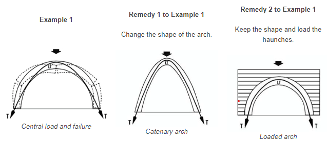
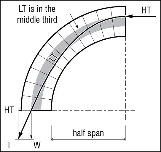
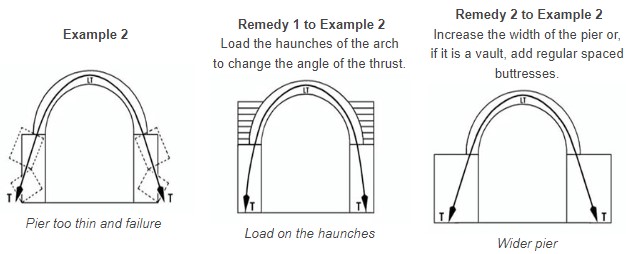
The line of thrust is in the middle third of the arch, but is not wide enough and will collapse.

CATENARY CURVE OF THE LINE OF THRUST

Arches can have various shapes and sizes, but the line of thrust always follows the shape of an inverted catenary curve.

A catenary is the curve assumed by a freely suspended chain or flexible cable under the action of gravity. The centre line of the links is the line of tensile stress. In an arch, the line of thrust is the line of compressive stress and takes the shape of an inverted catenary because it is the curve of natural load transfer in the masonry.

In an arch which has the shape of a perfect inverted catenary curve, the voussoirs correspond to the links of the chain. As the links of the chain are under tension, the voussoirs of the inverted catenary arch are under compression and LT is centred in the voussoirs. Catenary arches are always the most stable so their thickness can be reduced. Segmental arches are also very stable, as LT is near the centre of the arch.

The line of thrust is centred in the arch only in the case of inverted catenary arches. All the other types of arches will have LT moving in the middle third of the arch thickness, but it will never be centred. Therefore, the arch will be submitted to a combination of compressive and tensile forces, which will tend to induce failure.

As LT is the line of compressive stress, the entire arch will be stressed only under compression when LT is close to the centre. When LT moves away from the centre, but still remains in the middle third, this will create a tensile stress on the opposite side of the eccentricity of LT. To optimise the behaviour of an arch, one should try to get LT as close as possible to the centre.

Depending on the load applied on the arch, the line of thrust will assume a particular curve and the arch will be shaped accordingly:

MODIFICATION OF THE LINE OF THRUST IN A WALL

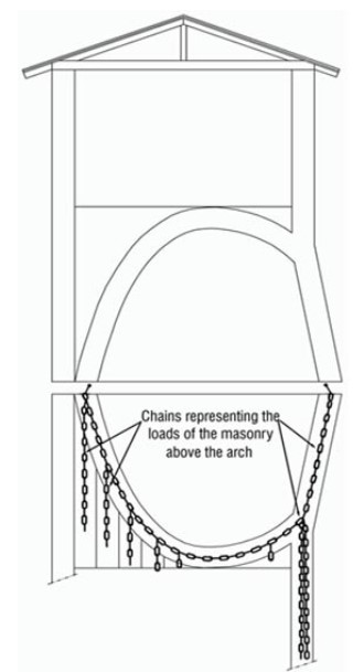
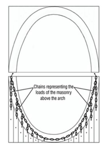
The arches shown as examples here are considered to be free standing, meaning without masonry above. Adding some load above the arch will modify the line of thrust in the masonry. LT will become a higher catenary, which often does not pass anymore in the arch but in the masonry above it.

Thus the principal line of thrust materializes a discharging arch. 
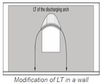
Therefore the original arch is supporting only its load and the “triangular load” of the wall, situated below the discharging arch. The arch will still have a line of thrust, and this triangular load will slightly increase its intensity. LT will pass more towards the arch extrados and exit nearer the intrados.

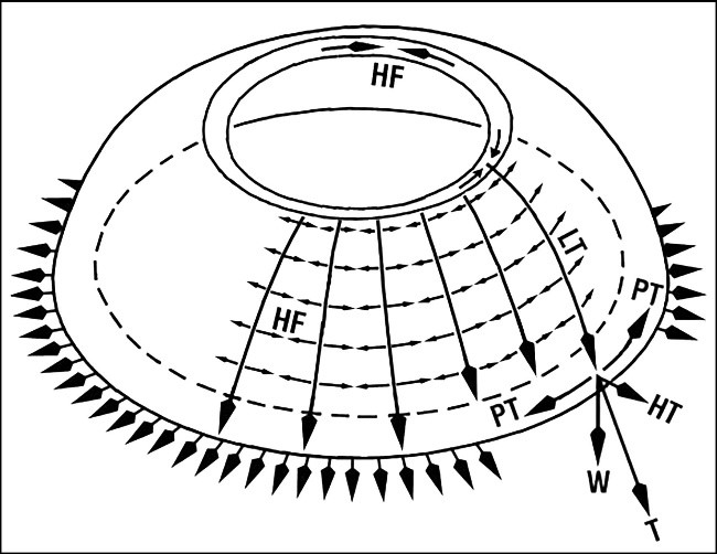
Note that here we use only the name arch but all this approach is also valid for a vault, as an arch generates a vault. We have seen that the line of thrust assumes the shape of an inverted catenary curve and should always remain in the middle third of the arch.

Semicircular arches have a very different profile compared to the catenary curve. Therefore, LT will move far away from the centre and this will create a lot of tensions in the arch. In order to get LT in the middle third of the arch, the thickness should be in relation to the span. Semicircular arches should have a minimum thickness of:
(Where t is the thickness and S the span)
Therefore a semicircular arch needs to be very thick to be stable without any load on the haunches: A 6 m span arch requires 1.20 m thickness, so as to get LT at the inner limit of the middle third.

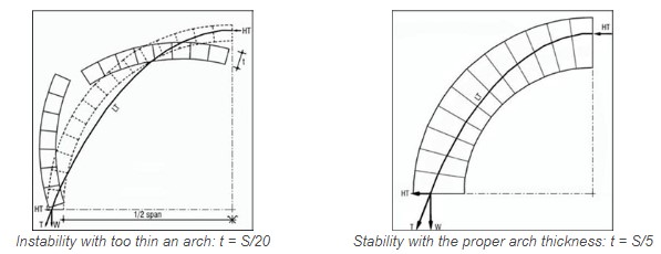
This relationship explains why the semicircular barrel vaults need to be very thick, as the haunches cannot always be loaded. Note that the thickness of a semicircular arch can be reduced if the haunches are loaded. This will have three effects:
1. LT will enter the middle third of the arch and it will become stable.

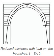
2. The load on the haunches will load the pier and bring the thrust more vertical. Thus, the width of the pier can be reduced also.

3. The horizontal thrust is decreased, but the weight and the resultant thrust are increased.

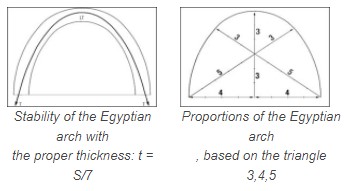
Similarly, an Egyptian arch needs to be relatively thick to be stable:
(Where t is the thickness and S the span)
Therefore an Egyptian arch of 5 m span will require 71.5 cm thickness, so as to get LT at the inner limit of the middle third.


The various methods for calculating the stability of arches and vaults, do not consider the effect of the mortar on the strength of vaulted structures. Calculations assume compression-only structures which are built with dry stacked masonry.

Generally speaking, mortar binds blocks together and transmits compression forces. At the intrados of an arch, forces are transferred directly from block to block: they touch each other. At the extrados of an arch, the contact is ensured by the mortar, which transmits compression forces when it is dry.

In general, mortars have a relatively low tensile strength. However, this can considerably increase the loadbearing capacity of an arch. Nevertheless, the tensile capacity of masonry is unreliable and therefore should not be considered for the stability of vaulted structures.

When vaults and domes are built with the Nubian or Free Spanning techniques, the quality of the mortar is essential to stick the blocks onto each other (See Section “5.2 Nubian Technique”, page 141). This cohesion is only required while building the structure. Once the structure is completed, the mortar achieves its dry compressive strength, is consolidated by compression forces in the arch, and the transmission of the forces occurs through the mortar.

EVALUATION OF THE STABILITY OF DOMES

We have seen that domes which are generated by the intersection of two vaults (i. e. groin and cloister domes), have forces similar to those of vaults. Therefore, the stability of these vaults can be studied like the arch of their cross section or generating geometry. Nevertheless, these kinds of domes have a structural behaviour which is different from that of their generating geometries: they will exert a thrust on four sides, which will require a ring beam or abutments to balance.

For a dome generated by the rotation of an arch around a vertical axis, the hoop forces which act in it cannot be calculated by the methods in this manual. These domes require another approach to calculate their stability.

The examples of domes built all over the world throughout the ages demonstrate that domes can have a wider variety of shapes than vaults. For instance, a dome can be conical with any proportions: either pointed or flatter. But it is obvious that an arch cannot have a triangular section, as a cone is a triangle rotating around a central axis.

Therefore, if arches or vaults are stable, domes of the same section will necessarily be stable. But the opposite is not necessarily true, as we have seen with the case of the conical dome and the triangular arch.

This gives the principle for studying the stability of circular domes: A cross section of the dome is studied as an arch and; when this arch is stable, the dome will necessarily be stable.

The accumulated horizontal thrusts create a peripheral tension which tends to crack the base of the dome and the support wall. This tension can be evaluated.

The 22.16 m diameter dome of the Dhyanalinga Temple for Lord Shiva, near Coimbatore-TN-India, was studied with this approach. The dome was built in 9 weeks without any difficulty concerning its stability. The dome has stood since January 1999.

The dome was built on the slope of a hill, and the foundations settled due to the enormous load of the structure: about 1,500 tons, which were built in less than 6 months.

Three months after completion, the ground – a black clay – settled unevenly, and one third of the perimeter of the foundations and wall moved a few millimetres outwards and downwards. Thus, the dome cracked above this settlement.

No reinforced concrete ring beam had been used for this dome, as it was a requirement from Swamy Jaggadish Vasudev, the Guru, to achieve a structure with a 1,000-year lifespan. The mass of the masonry wall was studied to neutralize the thrust.

Newsletter

Get all latest content delivered to your email !

Follow us on our social media to stay up to date on our activities!

Contact US